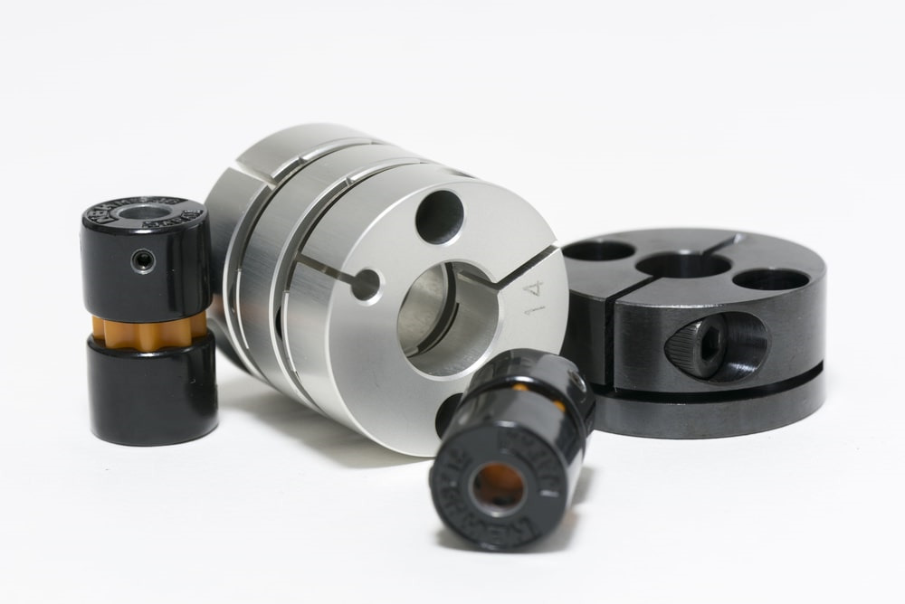
About Shaft Couplings
A shaft coupling is a mechanical part that connects the travel shaft and driven shaft of a electric motor, etc., as a way to transmit electrical power. Shaft couplings expose mechanical flexibility, offering tolerance for shaft misalignment. Because of this, this coupling versatility can reduce uneven dress in on the bearing, equipment vibration, and other mechanical troubles because of misalignment.
Shaft couplings are available in a small type mainly for FA (factory automation) and a big casting type used for large power tranny such as for example in wind and hydraulic vitality machinery.
In NBK, the former is 
Why Do WE ARE IN NEED OF Shaft Couplings?
Even if the motor and workpiece are straight connected and correctly fixed, slight misalignment can occur over time because of alterations in temperature and alterations over a long period of time, causing vibration and damage.
Shaft couplings serve as an important link to minimize impact and vibration, allowing simple rotation to end up being transmitted.
Flexible Flanged Shaft Couplings
Characteristics
These are the most used flexible shaft couplings in Japan that comply with JIS B 1452-1991 “Flexible flanged shaft couplings”.
A simple structure manufactured from a flange and coupling bolts. Easy to set up.
The bushing between your flange and coupling bolts alleviates the effects of torque fluctuation and impacts during startup and shutdown.
The bushing can be replaced by just removing the coupling bolt, enabling easy maintenance.
Permits lateral/angular misalignment, and reduces sound. Prevents the thrust load from simply being transmitted.
2 types can be found, a cast iron FCL type and a carbon steel?FCLS type Flexible Shaft Couplings
Shaft Coupling Considerations
In selecting couplings a designer first must consider motion control varieties or power transmission types. Most action control applications transmit comparatively low torques. Power tranny couplings, in contrast, are created to carry average to high torques. This decision will narrow coupling choice relatively. Torque tranny along with optimum permissible parallel and angular misalignment ideals will be the dominant considerations. Many couplings will publish these values and using them to refine the search should help to make picking a coupling style simpler. Maximum RPM is another important attribute. Optimum axial misalignment could be a consideration aswell. Zero backlash is an essential consideration where feedback is employed as in a movement control system.
Some power tranny couplings are created to operate without lubricant, which may be an advantage where maintenance is a problem or difficult to execute. Lubricated couplings generally require includes to keep the grease in. Many couplings, including chain, equipment, Oldham, etc., can be found either as lubricated metal-on-metal kinds and as metal and plastic-type hybrids where usually the coupling element is made from nylon or another plastic-type material to get rid of the lubrication requirements. You will find a reduction in torque ability in these unlubricated varieties when compared to more conventional designs.
Important Attributes
Coupling Style
Most of the common variations have already been described above.
Maximum RPM
Most couplings have a limit on the maximum rotational velocity. Couplings for high-acceleration turbines, compressors, boiler feed pumps, etc. generally require balanced patterns and/or balanced bolts/nuts allowing disassembly and reassembly without increasing vibration during procedure. High-speed couplings may also exhibit windage effects in their guards, which can cause cooling concerns.
Max Transmitted Horsepower or perhaps Torque
Couplings are often rated by their maximum torque capacity, a measurable quantity. Ability is certainly a function of torque situations rpm, consequently when these ideals are stated it is generally at a specific rpm (5HP @ 100 rpm, for example). Torque values are the additionally cited of both.
Max Angular Misalignment
Among the shaft misalignment types, angular misalignment ability is usually explained in degrees and represents the utmost angular offset the coupled shafts exhibit.
Max Parallel Misalignment
Parallel misalignment capacity is usually given in linear products of inches or millimeters and represents the maximum parallel offset the coupled shafts exhibit.
Max Axial Motion
Sometimes called axial misalignment, this attribute specifies the utmost permissible growth between your coupled shafts, given generally in inches or perhaps millimeters, and may be due to thermal effects.